


HDI Quality and Acceptability Requirements


The very nature of microvias’ small size makes the acceptability criteria difficult to define. Most HDI Quality and Acceptability requirements are still OEM defined. The IPC has IPC-6016 as part of the IPC-6012, the generic QUALIFICATION AND PERFORMANCE SPECIFICATIONS (6010 SERIES). These specifications only cover the build-up HDI layers and not the core, which is covered by their own IPC specifications.
IPC-6016 Qualification and Performance Specification for High Density Interconnect (HDI) Structures
IPC-6016: This document contains the general specifications for high-density substrates not already covered by other IPC documents, like IPC-6011, the generic PWB qualification and performance specifications. The acceptance criteria of HDI layers are organized into slash sheet categories of:
A. Chip Carrier
B. Hand Held
C. High Performance
D. Harsh Environment
E. Portable
The acceptability requirements are broken down into these 12 specific specifications:
- Section 3.1: General
- Section 3.2: Materials
- Section 3.3: Visual Examination
- Section 3.4: Dimensional Requirements
- Section 3.5: Conductor Definition
- Section 3.6: Structural Integrity
- Section 3.7: Other Tests
- Section 3.8: Solder Mask
- Section 3.9: Electrical Properties
- Section 3.10: Environmental Requirements
- Section 3.11: Special Requirements
- Section 3.12: Repair
Quality- Control
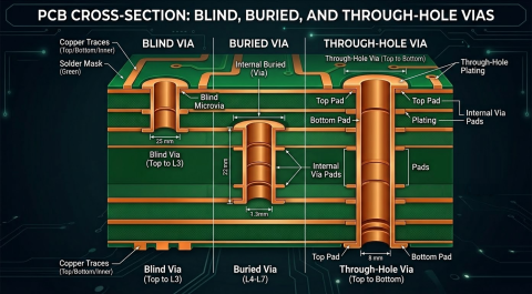
Microvias are nearly impossible to inspect visually and extremely difficult to cross-section. This necessitates a more indirect approach to verification of proper fabrication. Proper microvias, as seen in Figure 1 a-d, can be distinguished from defective microvias, as seen in Figure 2a-d. It is easiest to cross-section these vias when they are employed in a “test coupon” such as the IPC’s PCQRR program. These coupons are the same as used in IPC-9151 and correlate to a statistically measured via-chain resistance and accelerated thermal-cycling tests (HATS). [1] The criteria for quality microvia production are no more than 50 defective microvias per million microvias and a covariance of the standard deviations of the daisy chain Kelvin resistances coupons of 5%.
FIGURE 1. Example of well fabricated blind and buried vias; a. 8-Layer blind-buried vias; b. 6-Layer blind-buried vias; c. Skip blind via from L-1 to L-2 & L-3; d. Proper blind via filled with solder-mask.
FIGURE 2. Improperly formed blind vias that should be rejected.
Laser Drilling Quality
The quality of laser drilling of microvias illustrates the nature of the failure modes in microvias. Figure 3 shows the seven main quality criteria for laser microvias, along with the quality criteria spec, measurement methods, sample size and control limit.
FIGURE 3. The seven main quality criteria for laser-drilled microvias
Vendor Qualification
Selecting an HDI fabricator can be very challenging. One way to discover the HDI capabilities of PCB fabricators is the new IPC-9151 Capabilities Benchmarking Panel. This standardized multilayer panel can be seen in Figure 4. It is provided in 2, 4, 6, 10, 12, 18, 24, and 36-layer structures with high and low-density design rules, 5 thicknesses (for PCB and backplanes), and in a large panel size of 18” x 24” with various traces and spaces and via structures of blind and buried. The IPC Committee is planning other new Benchmarking Panels for substrates.
The blind vias are optional, but provide significant data on the fabricator’s HDI capabilities. Details, artwork, and a sample report are available on the IPC 9151 Website.
FIGURE 4. A typical PCQR2 panel from the IPC Program
Other options include fabricating production boards and having them tested. Although this method is convenient, most times this results in statistically non-significant results, that is; too few samples are evaluated to provide for statistically significant interpretation. The performance measured could be the result of hand-selecting the samples and not being statistically accurate in covering a range of capabilities.
Test Vehicles many times are used for qualification and this can be very accurate. This is also the way reliability can be established. Later sections will discuss test vehicles and reliability testing results
Qualification Coupons
The best tools I know for doing this are the many parametric analysis and characterization coupons available to you. These are part of the quality assessment process. These processes cover reliability evaluations, end-product evaluations, work-in-process product evaluations, and process parameter evaluations. Here are five coupon systems, four seen in Figure 5:
- IPC-2221 Appendix A, D-Coupon
- Conductor Analysis Technology (CAT™)
- Printed Circuit Quality and Relative Reliability (PCQR2) (Figure 4)
- Highly Accelerated Thermal shock (HATS™)
- Interconnect Stress Test IST™)
FIGURE 5. Four of the five qualification test coupons systems; a. IPC D-Coupon; b. CAT’s coupons for panels; c. CAT’s various HATS test coupons; d. Interconnect Stress Test (IST) coupon.
Accelerated Reliability Test Coupons
Three coupon methods are typically used in reliability test vehicles:
- Accelerated Thermal Cycling (ATC)
- Highly Accelerated Thermal Shock (HATS)
- Interconnect Stress Test (IST)
Thermal Cycling Testing
Accelerated reliability testing using test coupons is about as old as PCBs are. The principle is to crowd a large number of holes into a small space and connect them in a chain, hence the name ‘daisy-chain’. The test board pictured in Figure 6 is typical of an HDI daisy-chain test vehicle. This board contains a number of different test structures for various test criteria. Most of the space is taken up by the HDI blind-via daisy-chains (BLOCK A, B, C, E, and F) and the TH daisy chain (BLOCK D). Table 1 shows a summary of the test blocks and their criteria for qualification. Figure 7 is typical for the qualification of higher volume technology-intensive products like notebook computers and networking cards.
FIGURE 6. Typical HDI Qualification/Reliability test vehicle.
Many coupon systems are used for reliability testing. These are incorporated into test vehicles that are then fabricated and subjected to various conditioning and stresses and then evaluated for performance. The IPC has provided a new generation of test coupons, the “D-Coupons” from Appendix A in the IPC-2221 standard. The testing criteria for the 4-wire Kelvin resistance test are provided in IPC-TM-650, Method 2.6.27A. The thermal shock is per IPC-TM-650, Method 2.6.7.2.
These tests are carried out after the coupons are passed through an SMT convection reflow assembly oven for a minimum of 6 times using one of two different reflow profiles (230OC or 260OC) without any measured high resistances or open detected.
TABLE 1. Test criteria for HDI test vehicle.
FIGURE 7. Typical industry test vehicle for higher reliability computer and telecom products.
About Author
Related Resources
Related Technical Documentation
Table of Contents
Design to Release, Without the Friction
- Keep reviews tied to the right version
- Reduce handoff confusion and rework
- Spot sourcing and release risk earlier
- Work solo, share when needed
Get Started
Thank you, you are now subscribed to updates.