


Select the Right Microvia Aspect Ratio in Your HDI PCB


If you’re not familiar with PCB design or electronics in general, you probably wonder how newer electronics can pack so much functionality into progressively smaller devices. It takes more than just Moore’s Law, it takes creative PCB design methods to pack all that functionality into a single device. This gave birth to HDI design for densely packed circuit boards and small electronics, like smartphones and small form factor embedded systems.
Vias make their mark in multi-layer PCBs and are used to route connections between signal layers, or to connect signal layers to power/ground layers. In an HDI PCB layout, microvias need to be carefully designed to ensure they are reliable and will comply with manufacturer's capabilities. As boards get smaller and denser, it is tempting to make the switch to using microvias to create the required connectivity in a new device. Designing and routing with microvias requires selecting the right microvia aspect ratio as this is a major determinant of reliability and manufacturability.
Microvia Aspect Ratio
The term "microvia" is sometimes used to refer to any via with a diameter less than 6 mils. The official definition of a microvia, according to the IPC, is:
- “[a] blind structure (as plated) with a maximum aspect ratio of 1:1…terminating on or penetrating a target land, with a total depth (X) of no more than 0.25 mm [0.00984 in] measured from the structure’s capture land foil to the target land.”
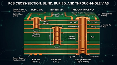
In other words, we have a limit not just on the diameter, but also on the aspect ratio for the structures we normally call microvias. This places limits both on where the microvia can be used in the board, as well as how large they can be or what they can connect to. If you look at the structure a typical HDI PCB that uses microvias, you will see a thick core layer stacked with smaller prepreg layers. These outer layers will support microvias, through-holes, or typical buried vias. However, the core layer is thick enough that you won't be able to meet microvia aspect ratio targets, so only a drilled buried via should be placed in the core layer. The image below shows how microvias are normally arranged alongside standard through-hole or mechanically drilled buried vias through the thicker central core/prepreg layers.

In terms of a simple formula, the microvia aspect ratio is defined as:
Microvia Aspect Ratio = (Dielectric Thickness on Outer Layer + Outer Copper Foil Thickness) / Microvia Diameter
Therefore, it's not just the dielectric thickness that matters, it's also the copper weight that's important. The above formula suggests that you can use a thicker copper foil on the land to accommodate a larger microvia diameter while still hitting a target microvia aspect ratio. The microvia aspect ratio definitions shown here apply to blind microvias on the outer layer or buried microvias connecting between inner layers.
The primary consideration in HDI design is to select a microvia aspect ratio that will ensure reliability and can be fabricated with high quality. This is important because, in 2019, the IPC issued an important reliability warning about the use of large aspect ratio microvias in stacked arrangements; in some reliability studies, it was found that large aspect ratio microvias were prone to failure during reflow cycles. This prompts the use of larger microvia diameter, thinner copper foil on the land, or both. The aspect ratio of a microvia also presents different types of challenges during fabrication, and going to an overall smaller microvia for a given aspect ratio requires a different drilling process to keep costs down, particularly in thinner dielectrics.
Types of Microvias
Microvias can generally be placed in any standard PCB dielectric material, whether it's a glass-reinforced epoxy laminate or resin coated copper foil (RCC) materials. They can be fabricated by mechanical drilling (for larger diamaters), or with laser drilling (for smaller diameters and aspect ratios). The typical structures of microvias are:
- Blind microvias: These microvias span from a surface layer to the very next layer in an HDI stackup. These structures may be filled with copper or left unfilled, although microvia-in-pad designs should use filled structures to provide a uniform placement for soldering.
- Buried microvias: These microvias are basically blind vias that are confined to internal layers. They also must obey the standard aspect ratio requirements to ensure reliability and manufacturability. Buried vias should be filled with the appropriate process to ensure they can withstand the stress they might experience in reflow or thermal cycling during operation.
- Skipped microvias: The microvia is formed in one operation where two or more HDI dielectric layers are spanned by the length of the via. These microvias are best used to span across thinner dielectrics as this is the best way to ensure you can make the desired connection while maintaining the required low microvia aspect ratio.
In terms of the design requirements for these structures, larger aspect ratios should be staggered as shown in the cross-sectional image above, while you may be able to get away with stacking microvias with smaller aspect ratios. Make sure to contact your fabricator as they should be able to advise on the reliability and yield of microvias in their process.
Microvia Fabrication Processes
Mechanical drilling can be used to place larger diameter microvias, but it does not carry any limit on aspect ratios. It can be useful when the dielectric thickness is larger, and it will already be used to place through-hole vias and any buried vias passing through the core. However, on thicker dielectrics, a very thin drill might bow during fabrication, which might create some mis-registration. Note also that mechanical drills can only survive fewer drill hits, and the survival time reduces when the dielectric thickness is greater. For this reason, it is often better to stick with a thinner dielectric (~4 mils) when using drilled microvias.
Laser drilling is used for fabricating smaller diameter microvias, but the depth of focus of the laser beam only allows these microvias to cross a single layer in a thinner dielectric. These vias typically have less than 1:1 aspect ratio, depending on the drill depth and the diameter of the via hole. Longer stacked structures require multiple laser hits, which may carry less misregistration probability than mechanical drilling.
Note that, at least for internal buried microvias, you can't simply move to thicker copper to artificially increase the aspect ratio of the microvia or to try and increase the reliability of the board. The reason is that the neighboring prepreg layer may not totally fill voids around the land of the microvia during pressing, particularly when the resin content is low. For very dense fiberglass weave prepregs, like spread glass weaves (7628), the resin content will be low enough that there may be some voids leftover around the land. This is quite important because HDI designs tend to run at higher speeds where fiber weave effects may become important. To learn more about this issue with copper thickness on internal layers, read this recent article.
BGA Breakout and Board Thickness
Typically, the design guides used in HDI PCB design don't care about the overall thickness of the layer stack unless a through-hole is needed through the entire PCB stackup. Instead, we generally only focus on the dielectric layer thickness when discussing HDI PCB design and microvia aspect ratios. Once the size of your board reaches a certain thickness and layer count, standard through-hole vias are no longer useful for BGA breakout in fine pitch BGAs: the aspect ratio of these through-holes becomes too large and you will want to use microvias. As an example, think about the case of BGA breakout routing using through-hole vias. Drilling limitations would require that you use vias with wider holes in order to breakout from the BGA. This then requires the use of a BGA with coarser pitch and consumes valuable real estate. Your components might not allow this due to pitch limitations:
- At larger pitches, solder mask defined (SMD) pads can be used with microvias in dog-bone fanout
- 0.5 mm and smaller pitch will often require microvias, although this depends on fanout
- At less than 0.5 mm pitch, it's possible to use 6 mil mechanical drills in-pad, but the pad size may not leave enough annular ring to comply with IPC standards
Higher pin density components, like high ball count BGAs with small pitch, eventually require microvias to breakout traces from beneath the component. As you get to higher pin densities, such as in advanced processors with hundreds or thousands of pins with low pitch, the typical dog bone fanout strategy is no longer useful and the BGA must be attached directly to via pads. BGA pads that are less than 0.5 mm may not be able to accommodate mechanical drilling without increasing fabrication costs. When we get to very fine pitch, like 0.35 mm BGA components, laser-drilled microvia-in-pad may be needed to mount these components on your PCB.

A Process for Microvia Sizing
Once you've decided on an upper limit for the aspect ratio in your design, and you've determined an appropriate standardized HDI stackup, you can use the layer thickness to determine the appropriate microvia size:
- Select a standard HDI stack-up and layer thicknesses.
- Based on layer count and thickness, select appropriate laser-drillable prepreg materials for buildup layers
- Using the aspect ratio upper limit, determine the lower limit on the hole size and pad size required for your microvias.
- If hole/pad sizes in #3 will not work beneath fine-pitch components (BGAs), then the layer thickness may need to decrease.
- If the buildup layer thickness cannot be decreased, then the allowed aspect ratio upper limit may need to increase
In Step 4, decreasing the layer thickness allows for a smaller lower limit on the hole size based on the desired aspect ratio. The other option in Step 5 can arise when a thinner layer option is unavailable or if you have already reached the low end of allowed layer thickness values. In either approach, this will allow you to determine the lower limit on hole size and pad size for your microvias; you can still use larger microvias where needed as long as they can satisfy etching clearances in PCB fabrication.
Summary
The information and guidelines shown above are applicable for a broad range of products that are designed with HDI principles. However, you should still contact your fabricator and get their recommendations on stacking and staggering blind/buried vias for different aspect ratios. Make sure you communicate your design requirements, namely smallest pitch BGA, ideal layer count, and whether you're using non-standard PCB thickness. They should also be able to give you a basic stackup that they can support in their process and that is known to produce reliable fabrication results.
The advanced layout and routing features in Altium Designer® are built on top of a rules-driven design engine, making it easy to enforce the microvia aspect ratio you need for your design. The routing features in Altium Designer will help you automatically enforce microvia aspect ratio limits in your interconnects as you design your HDI PCB.
We have only scratched the surface of what is possible to do with Altium Designer on Altium 365. Start your free trial of Altium Designer + Altium 365 today.

About Author
Related Resources
Related Technical Documentation
Table of Contents
Design to Release, Without the Friction
- Keep reviews tied to the right version
- Reduce handoff confusion and rework
- Spot sourcing and release risk earlier
- Work solo, share when needed
Get Started
Thank you, you are now subscribed to updates.

