


2+N+2 PCB Stackup Design for HDI Boards

At a Glance
A 2+N+2 PCB stackup is one of the standard options for building a high density circuit board. Learn more about these stackups for HDI PCBs.


Like any other advanced PCB, success in HDI design comes from designing the right stackup. While this is certainly true in terms of signal and power integrity, it also matters for manufacturing; the HDI PCB stackup you use must conform to a set of standard processing steps required to build up the board. According to the IPC-2226 HDI PCB standards, there are several types of standardized HDI PCB stackups that
One common HDI stackup used to support routing into moderate pin count, high-density BGA components is the 2+N+2 PCB layer stack for HDI boards. This stackup uses sequential lamination with multiple HDI layers and a conventional inner layer to build up the layer stack. We’ll explore this stackup more in this article, as well as how it is related to other advanced stackups used in HDI PCBs.
About the 2+N+2 PCB Stackup for HDI
The structure of a 2+N+2 PCB layer stack structure is defined in the IPC-2226 standards (known as Type III); this structure is shown below. This diagram is an exploded view of the layer stack to show the number of sequential laminations in the top/bottom portions of the stackup, as well as the buildup process for this PCB stackup. The top layers are the HDI routing layers, where microvias are used on thin dielectrics to access the interior layers in the stackup. The “2” in 2+N+2 refers to the fact that two sequential lamination steps are needed in the PCB stackup so that the two upper HDI layers can be stacked on the inner layer section.

i+N+i PCB Stackups
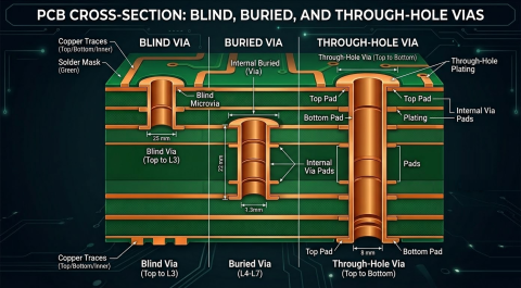
More generally, this structure is known as an i+N+i stackup, where the outer sections consist of i sequentially laminated layers connected with microvias. The inner portion of the layer stack is connected to the outer sections at the top and bottom ends with a buried via, and the buried via portion (called a core via) also connects to the other inner layers. You could conceivably use any number of sequentially laminated layers on the outside of the stackup as long as it can be produced by your fabrication house. For example, 3+N+3 and 4+N+4 layer stacks are also common options provided by HDI PCB fabrication houses.
Also, there is technically no limit to N in theory, although practically this will be limited depending on the outer layer thickness and the total layer count. The reliability issues (to be discussed more below) found in microvia stacks is not present on this inner layer as a mechanically drilled through-hole is used to connect the inner layers before lamination with the outer layers. This forms a buried via once the entire stackup is built up. Once the stackup is built up, through-holes can also be placed in the finished layer stack going between all layers using standard drilling and plating processes.
Sequential Lamination (or Buildup)
The standard process used to build the stackup for an HDI PCB is sequential lamination. Effectively, the stackup is fabricated by forming each layer individually, then the entire 2+N+2 stackup is formed with a final lamination step. The most common material types used in sequential lamination for HDI stackups are resin-coated copper (RCC), specifically metalized polyimide, pure polyimide, and cast polyimide. PTFE and FR4 laminates are also used in HDI layer stackups.
Some fabrication houses will tell you that you cannot use stacked vias in a stackup created with sequential lamination, but I think there is some confusion on this point. The 2+N+2 structure can support stacked vias, including with the core via possibly extending into one of the sequentially laminated layers. I think the confusion comes from implementing a stacked via to span two layers as defined in the Type I HDI stackup (see below). Instead, we would use skip vias to route from the surface layer into an inner layer, and this layer pair would be laminated onto the core via layer.

Other Standardized HDI Stackups
The 2+N+2 stackup is probably the most popular HDI stackup that supports high pin count BGAs, but there are other stackups that are defined in the IPC-2226 standards. These are labeled Type I to Type VI with progressively increasing complexity. These types of stackups are shown below:

Over-core (Type IV) involves depositing dielectric over an internal core layer and is less common among HDI stackups. The most complex is Type V/VI, better known as every layer interconnect (ELIC), where stacked/staggered microvias are placed throughout the stackup.

Among these, Type I to Type III (2+N+2) are most common. Note however, that some fabricators will recommend you avoid exceeding 2+N+2 or 3+N+3 stackups either due to capability or yield issues. They will tell you to instead focus on a fanout strategy to fit all the traces you need into each layer and to touch high pin count BGAs. I would agree with this, but if a 4+N+4 stackup was needed, I would look for a fabrication house that just supports ELIC.
When you’re ready to program your 2+N+2 stackup into your ECAD tools, use the Layer Stack Manager in Altium to define your HDI stackup and create your routing rules. You and your team will be able to stay productive and collaborate efficiently on advanced electronics designs through Altium. Everything you need to design and produce advanced electronics can be found in one software package.

About Author
Related Resources
Related Technical Documentation
Table of Contents
Design to Release, Without the Friction
- Keep reviews tied to the right version
- Reduce handoff confusion and rework
- Spot sourcing and release risk earlier
- Work solo, share when needed
Get Started
Thank you, you are now subscribed to updates.

