


From HDI to Ultra HDI: Via Structure in PCB Design

At a Glance
Explore how Ultra HDI technology is revolutionizing PCB design with smaller vias, higher routing density, and better performance for advanced electronics applications.


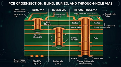
If you’ve been working with HDI (High-Density Interconnect) technology, you’ve probably noticed that the industry is pushing the boundaries of what's possible. Traditional HDI designs have relied on laser-drilled microvias around 4 mils in size, with capture pad diameters typically 8–10 mils larger. But technology never stands still, and now Ultra HDI is taking things to a whole new level, redefining via structure and density in ways that were previously unthinkable.
Ultra HDI: Reducing Size
Ultra HDI technology is all about pushing printed circuit board feature sizes to the extreme, and that includes not only traces but microvias. We’re now looking at via sizes as small as 2 mils, with absolute minimum capture pads of 6 mils—though 8 mils is still a sweet spot for reliability. To put that into perspective, this means you can have a 75-micron via with an 8–10 mil capture pad, dramatically shrinking your PCB footprint and enabling the use of high-density components.
Why does this matter? Because as electronic devices become more complex and compact, the demand for higher interconnect densities continues to grow. Ultra HDI makes it possible to pack more functionality into smaller spaces without sacrificing reliability. It’s a game-changer for industries pushing the limits of miniaturization, such as aerospace, medical devices, and high-performance computing.

The Technology Behind Ultra HDI
So, what makes Ultra HDI possible? The answer lies in advanced build-up technology, ultra-thin materials, and precise via filling techniques.
First, let’s talk about build-up technology. Ultra HDI relies on incredibly thin dielectric layers and ultra-thin copper foil (e.g., 1/4 oz./sq. ft. copper weight) to achieve its tight tolerances. These thin materials allow for the fabrication of finer features with tighter tolerances than coarser etching, which helps maintain signal integrity on thin layers. The key to making this work is keeping the via aspect ratio (material thickness to via diameter ratio) below 1:1. For example, if you’re designing a 2 mil via, your dielectric layer must be less than 2 mils thick. This typically means working with 35-micron or even 25-micron dielectrics. A slightly larger 3 mil via might allow for a 2 mil dielectric, but in every case, precision is critical.
Then, there’s the challenge of filling buried vias in the internal ultra-HDI layers. At these scales, resin filling of staggered buried vias just won’t be a reliable option because PCB material resins will have difficulty filling the open space in a buried via. Instead, vias must be copper-filled to ensure reliable electrical performance and structural integrity. Copper-filled vias enhance signal integrity and thermal performance, both of which are crucial for high-frequency applications and designs with extreme space constraints. By eliminating air pockets and improving conductivity, copper filling helps make Ultra HDI reliable.

Ultra HDI Impact on Via Structures
One of the biggest advantages of Ultra HDI is the ability to consolidate trace routing for high-speed signals into a smaller number of layers. For example, an HDI design that required 2 mil minimum trace width and 4 mil minimum via diameter can achieve much higher density as an ultra-HDI design with 1 mil width trace and 2-3 mil via diameter. With smaller vias and thinner dielectric layers, designers can route more traces per square inch into a high-density component at thinner trace widths at the same impedance as on thicker layers.
Additionally, Ultra HDI improves power distribution and thermal management. The use of copper-filled vias enhances heat dissipation, which is essential for high-power applications. The smaller via structures also reduce parasitic capacitance and inductance, leading to better performance in high-speed and RF designs. As a result, industries requiring precise signal performance, such as telecommunications and advanced computing, are rapidly adopting Ultra HDI to meet their evolving needs.
The impact on via structures is profound. Traditional through-hole vias and even conventional microvias are no longer sufficient for next-generation designs. Ultra HDI enables stacked and staggered via structures with tighter pitches, improving layer interconnectivity and design flexibility. This allows for more efficient use of board real estate and enhances reliability in mission-critical applications.
Early Planning and Fabrication Partnership
Ultra HDI technology is exciting, but it also introduces new complexities. With such tight tolerances and advanced materials, fabrication isn’t something you can take for granted. That’s why early collaboration with your PCB fabricator is essential.
Designing for Ultra HDI isn’t just about shrinking vias; it’s about ensuring the entire process—from material selection to manufacturing techniques—is optimized for success. Working closely with your fabricator during the design phase helps identify potential roadblocks before they become costly issues. Given the precision required, even small adjustments early on can prevent major headaches later.
Pushing technology to this level can come with added fabrication costs. But a proactive approach can help mitigate those expenses. By partnering with your fabricator early, you can ensure process optimizations are in place, reducing the risk of costly redesigns and improving overall manufacturability.
If you’re working on designs that demand higher density, better signal integrity, and top-tier performance, Ultra HDI might be the solution you’re looking for. But remember, success with Ultra HDI starts with planning. Engaging with an experienced fabricator early in the process can make all the difference between a design that works and one that needs costly rework.
About Author
Related Resources
Related Technical Documentation
Table of Contents
Design to Release, Without the Friction
- Keep reviews tied to the right version
- Reduce handoff confusion and rework
- Spot sourcing and release risk earlier
- Work solo, share when needed
Get Started
Thank you, you are now subscribed to updates.