


PWM in Power Supply Design

At a Glance
PWM signals are used to control average power delivery in switching regulator circuits.


As their name implies, switch-mode power supplies use a semiconductor switch (typically a MOSFET) to drive a magnetic component, typically a transformer or an inductor. The output of the switched power circuit is then rectified and regulated to provide a DC output. Switch-mode power supplies are popular due to their significantly higher efficiencies over non-switched alternatives such as linear regulators. In this article we will tackle what is PWM control and how to use it.
What is PWM
Pulse width modulation (PWM), also known as pulse-duration modulation (PDM), is a technique for reducing the average power in an alternating current (AC) signal. PWM meaning is effectively chopping off parts of the waveform to reduce the average voltage without affecting the base frequency of the signal. Increasing the period when the voltage is 'off' reduces the average voltage, hence the power.
When applied in a power supply or a power regulator, PWM is applied to maintain either:
- Constant current output with varying voltage (current-mode control)
- Constant voltage with varying current (voltage-mode control)
More on this is discussed below. If we look at a time-domain waveform of a PWM signal, it would look like the waveform in the next image.
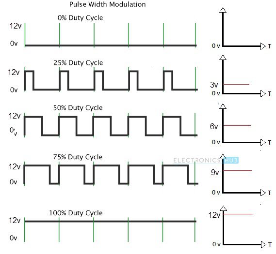
Image source: ElectronicsHub
Using PWM Output Control
Switch-mode power supplies must implement a feedback control loop to maintain their output PWM voltage control with the required limits under changing load conditions—the output voltage of the power supply feeds back through an error amplifier to provide a control signal. The most common control method is the use of PWM. The pulse width of the AC signal at the power supply's input is adjusted to increase or reduce the electrical energy, which in turn translates to a change to the voltage at the output of the power supply. For example, increase the input pulse width and the output voltage rises, decrease the pulse width, and reduce the output PWM voltage control. This mechanism provides closed-loop feedback control of the output voltage.
One issue to bear in mind is that a typical AC waveform tends to have benign rising and falling edges. The rising and falling edges can become more abrupt when PWM power supply control is applied, particularly with smaller duty cycle. Sudden voltage changes can generate transients, contributing to electromagnetic noise and causing large inrush currents within the PWM circuitry. Also, minor errors in the control circuitry can be amplified to significant output errors, potentially resulting in an unstable output voltage. A standard solution is to avoid abrupt on-off switching of the input waveform and instead limit the rate of change using a slope compensation technique.
Peak current-mode control (PCMC) techniques offer a simple solution for the Pulse Width Modulation (PWM) power supply circuit, except for inductor-inductor-capacitor (LLC) converters that require voltage-mode control. PWM power control will always be challenging when duty cycle approaches its maximum value. Designing the PWM circuit to avoid this situation is always preferable to adding additional control circuitry to apply slope compensation to prevent output instability.
Design Considerations
Transient Startup Currents
One of the drawbacks of switch-mode power supplies, particularly when used in isolated power supplies, is that a sizable transitory current may be caused by the energizing of the inductive elements of the power supply when switched on. In addition, the initial current is not predictable; it will vary with the exact point in the AC cycle when the inductive elements are first energized.
The transient response can be easily predicted in a SPICE simulation. You don't always need an exact model of the regulator, just a PWM signal that controls the FETs and mimics the rise/fall time of the actual PWM signal in the device. This is gives reasonably accurate results for gate drivers that are used to control external FETs, such as in an H-bridge. An example below shows a case where the passvies in a buck converter have insufficient ESR, leading to an underdamped response that is characteristic of an LC circuit during the first 500 ms of turn-on.

PWM-based control circuits can implement a soft-start feature that can control the initial power-on phase to limit the energy available to the PWM circuit and limit the energizing current until the power supply reaches a steady-state condition. Essentially, this would produce a damped turnon so that the above oscillation does not occur. Limiting the initial surge current protects components and can reduce emissions associated with transient current flow.
Many power regulator ICs will include this feature, which will be accessible with a pin on the device. An example is the LTM8052 from Analog Devices; the soft-start time on this device is programmed by connecting a capacitor to the SS pin.

Overcurrent Protection
A benefit of PWM control is that current sensing logic can be used to disable the power supply by switching the PWM off if the output current exceeds a defined limit. This offers a simple-to-implement overcurrent protection mechanism that automatically resets once the current returns within its boundaries.
Managing Low Loads with Pulse Frequency Modulation
One of the main drawbacks of a switch-mode PWM power supply circuit diagram is its inherent inefficiency at very low loads. Under no-load conditions, the power supply will continue to incur losses due to the power supply control circuitry. This can be an issue for battery power devices that operate for long periods in a standby mode where the power supply's efficiency determines battery life.
A solution to this situation is Pulse Frequency Modulation (PFM) in place of a PWM power supply circuit diagram. Here, the duty cycle of the AC waveform is unchanged, and the control of the power supply output is through a change to the frequency of the AC input.
The main problem with PFM is that noise filtering design becomes far more challenging due to the generation of noise over a much wider range of frequencies.
Other issues are that PFM control will generate a significantly greater output voltage ripple than PWM control and that the transient response time can be considerably longer. These issues make the designer's task harder if the power supply drives components sensitive to voltage fluctuations, particularly integrated circuits.
Power supply chips are now available with built-in dual-mode PWM circuits and PFM control that automatically switches based on the output load. Therefore, limiting PFM control to low load conditions will, by definition, minimize the effect of adverse effects such as emitted noise and voltage ripple.
Managing Low Loads with Pulse Skip Modulation
Another technique for managing low load conditions is to switch off the PWM waveform for a short period and rely on the power supply's output capacitor to maintain the output voltage during this period. This process of disabling the PWM waveform is known as pulse skipping or pulse-skip modulation (PSM). Under no-load conditions, the PWM waveform would only require intermittent enabling for short periods to compensate for losses in the power supply itself that drain the output capacitor.
An example showing the waveforms in a PSM-capable power regulator is found below. The PSM function eliminates a PWM pulse to the FET gates under conditions defined in the controller's internal circuitry. The example below comes from the TPS61175 from Texas Instruments.

Conclusion
The main advantage of using PWM circuits is very low power losses thanks to their high efficiency, utilizing very high frequencies for optimal circuit design. It is also relatively cheap to implement compared to comparable techniques for power supply design, with the ability to handle high loads. The main disadvantage is the additional complexity required to manage low loads. However, the availability of integrated devices that combine PWM control with automatic low-load management has simplified this task for the power supply designer.
About Author
Related Resources
Related Technical Documentation
Table of Contents
Design to Release, Without the Friction
- Keep reviews tied to the right version
- Reduce handoff confusion and rework
- Spot sourcing and release risk earlier
- Work solo, share when needed
Get Started
Thank you, you are now subscribed to updates.

