


High Speed PCB Design Review: Signal Integrity Questions You Should Always Ask

At a Glance
PCB design reviews encompass many parts of a design, ranging from basic circuits to manufacturability. For high-speed digital systems, a design review needs to be more specific and focus on areas that are not typically covered in standard manufacturability reviews.


PCB design reviews encompass many parts of a design, ranging from basic circuits to manufacturability. For high-speed digital systems, a design review needs to be more specific and focus on areas that are not typically covered in standard manufacturability reviews. The tools and process required to fully review a high-speed PCB design for signal integrity depends on the exact interfaces present in the design, but comparing against some rules of thumb and some basic calculations can help you avoid many of the simpler signal integrity problems.
Can They Build Your Stackup?
High-speed designs that require impedance control only function correctly when the stackup is fully specified, either by the designer or the manufacturer. While manufacturers can provide a standard PCB stackup, not all manufacturer standard stackups will be appropriate for high-speed PCBs. This is due to many factors, the most common being dielectric thickness and required trace width values in designs that need impedance control. As many digital designs require the use of BGAs, including fine-pitch BGAs, standard stackups might also not support the vias required to route into these components.
This means that you as the designer will have to take control over the design of the PCB stackup. And as part of the design review for your high-speed digital system, you will have to verify the fabrication house can build the stackup you specify. This is why it becomes important to familiarize yourself with the commercially available materials on the market because you can specify these in your stackup design and get quick verification from your fabrication house that they can build the PCB stackup.
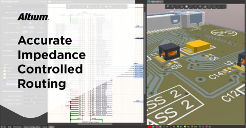
Are Impedance Calculations Accurate?
Because this question depends on the stackup construction, it has to be answered after the previous question. To first verify the stackup construction, produce your fabrication prints with a stackup table first, then check the stackup and PCB layout for the trace width and clearances after manufacturer verification.
Once the stackup construction is confirmed, there are several calculators that can be used to determine the trace impedance and check the design against the data in the PCB layout.
- Designers can use the calculator links located on these linked pages:
- Altium users can use the impedance calculator in the Layer Stack Manager
- External utilities like SI9000 from Polar Instruments can be used
- More advanced simulators and field solvers can provide S-parameters
- If none of these options work, there is a variety of online calculators available
The trace width values, and spacing for differential pairs, should be used to get an estimate of the impedance with one of these additional calculator options. You should then go back and check this for all of the impedance-controlled nets in the design.
If you are looking at the native PCB files, such as in Altium, there is likely a net class which you can select and manually check the width/spacing of all the traces in the net class. If you are reviewing manufacturing outputs, a CAM viewer can give the trace width values, or you can request the data from the responsible PCB designer.
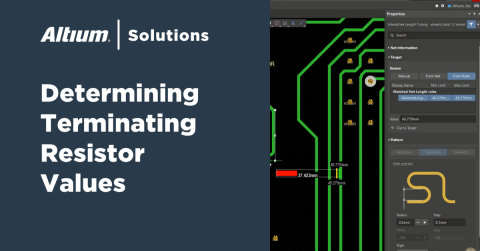
Timing Requirements
Digital systems can include a range of timing requirements, depending on the components and circuits in the design. In the past, system clock routing was at lower frequencies and was not synchronous with all interfaces, making timing requirements at the system level quite difficult. Today, high-speed interfaces use embedded clocks or source synchronous clocks, which move the timing requirements from the system level to the interface level.
In order to determine interface functionality, we need to perform a basic review of parallel interfaces, source-synchronous clocked interfaces, and mixed interfaces with embedded clocks:
|
Source-synchronous interface |
Embedded clock interface |
|
|
|
|
|
As we can see above, timing requirements need to be verified for both differential and single-ended interfaces, requiring a check on the delay tuning applied in the design.
Conductor Clearances
Clearances between conductors are both a manufacturability review item and a high-speed PCB design review item. In a high-speed PCB, we primarily concern ourselves with two areas:
- Spacing between single-ended traces and differential pairs
- Clearances to nearby coplanar copper pour (if it’s present on a signal layer)
The primary reason is to ensure crosstalk is minimized as large spacing between conductors is the easiest way to control crosstalk.
Determining the right trace-to-trace spacing to minimize crosstalk involves use of a simulation, including basic simulations that can be performed with a MoM/BEM method in your PCB design software. For example, the Signal Integrity tool in Altium Designer can be used to get a basic estimate of crosstalk for a specific rise time. After comparing the result to your noise margins in your receiver and performing the simulation on multiple layers, you can identify a good initial estimate for clearances between high-speed nets.
A simple example with 3.3V logic creating crosstalk in a victim trace is shown below, which was computed with the Signal Integrity tool in Altium Designer (now part of Altium Develop). The process for converging to an ideal trace spacing value will be discussed in other articles.

If you do not know how to determine the crosstalk between two traces or you do not have a calculator application that can do these calculations, you can set a 3W spacing requirement between high-speed nets. This is a large enough spacing for most designs, including down to very thin layers in UHDI PCBs.
For Final Review, Simulations Can Help
A manufacturability review and BOM review are always a good idea, even in high-speed PCB designs. But for signal integrity concerns, these other reviews are insufficient for verifying signal integrity related to the above areas. Instead, you will need a way to quickly port your design over to a simulation application so that the above areas can be verified.
- Ansys CoDesigner for design simulation in SIwave, HFSS, etc.
- SI Analyzer by Keysight for timing and impedance visualization
- ODB++ exports for use in Simbeor to examine channel compliance
Finally, a simple DRC check will identify standard manufacturability issues and constraint violations which impact all types of PCB designs, including a high-speed PCB layout. If you’ve done a thorough capture of manufacturer capabilities and fabrication limitations, then you can incorporate these into your PCB design rules and perform comprehensive checks when the PCB layout is completed.
Whether you need to build reliable power electronics or advanced digital systems, Altium Develop unites every discipline into one collaborative force. Free from silos. Free from limits. It’s where engineers, designers, and innovators work as one to create without constraints. Experience Altium Develop today!
About Author
Related Resources
Related Technical Documentation
Table of Contents
Design to Release, Without the Friction
- Keep reviews tied to the right version
- Reduce handoff confusion and rework
- Spot sourcing and release risk earlier
- Work solo, share when needed
Get Started
Thank you, you are now subscribed to updates.

