


How to Match PCB Via Types to BGA Pitch

At a Glance
BGA packages come in multiple pitch values, each of which demands a specific via size for fanout routing on the PCB.


The main component that tends to drive stackup design in high-density PCBs is the BGA. Specifically, the BGA pitch will be a major factor determining how to design the stackup and what via spans should be used for routing. Due to the ball pitch on a BGA package, there will be an upper limit on the via size and pad size that can be used for fanout routing. This will also determine whether via-in-pad is needed to complete the fanout.
I have discussed this in other contexts, specifically in terms of footprint design and selecting a trace width, but this only applied to dog-bone fanouts and packages with coarse ball pitch. This article will go deeper by looking at a range of pitch values and the via hole/pad sizes that can be accommodated. We will see from the discussion, this is a major driver of stackup design and can determine whether you can use a standard build, sub-lamination build, or HDI build.
How the PCB Stackup and BGA Determine Fanout Vias
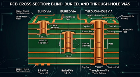
Large BGA packages are most often the major component determining allowed via sizes because the vias will be needed for fanout routing. Signals will not be able to reach inner rows of pins on the package without these vias, so these vias need to fit inside the BGA footprint region. Two factors must be balanced when sizing the vias and determining the type of stackup:
- Clearance between BGA pads and via pads
- Allowed aspect ratio for the vias based on drill diameter
This is always a tough optimization because smaller clearance will demand smaller drill diameter to accommodate a smaller via pad and annular ring. However, smaller through-hole drill diameters may be prohibited based on the copper weight and board thickness, and this forces the use of a sub-lamination or sequential lamination stackup build.
To determine the right build type, and possibly avoid an expensive HDI build, I go through the following process to determine the appropriate via size, via span, and build type:
- Determine the BGA pad size that is needed in assembly based on a preferred copper weight value.
- Determine the largest allowed pad sizes in dog-bone and via-in-pad fanout options for through-hole vias.
- Determine the maximum drill diameter for each fanout option based on the annular ring requirements.
- Compare the allowed drill diameter to the proposed board thickness and determine whether the aspect ratio can be fabricated.
- If the via is within aspect ratio limits for through-holes, then this initial design is acceptable.
- If the aspect ratio assuming through-holes is too large, then consider a sub-lamination build or HDI build.
- If the required drill diameter is less than 6 mil (0.15 mm), then HDI is required.
- In 4b, if a sub-lamination build with blind vias is selected, then determine the final copper weight after plating and verify the clearances in the BGA are still sufficient.
Via Sizing Examples With Two BGA Packages
Consider the examples shown in this section. I'll look at two components: a 0.8 mm pitch package and a 0.5 mm pitch package. The 0.8 mm pitch package is very close to 1.0 mm pitch, and very similar practices are used in both devices.
Example 1: 0.8 mm BGA Package
First, take a look at the 0.8 mm pitch device shown below. This BGA has X mm/Y mil distance between the pad edges along the diagonal direction.

These large vias can be used in dog-bone fanout with a 0.8 mm pitch BGA, but typically smaller vias might be used.
If we start with a 0.1 mm/4 mil clearance limit, we could fit the following via pad and drill size between the pads for a dog-bone fanout or via-in-pad fanout:
- Dog-bone fanout:
- Maximum via pad size: 20.8 mil
- Maximum via drill hole size: 12.8 mil for Class 2 or 10.8 mil for Class 3
- Via-in-pad fanout:
- Maximum via pad size: 27.6 mil
- Maximum via drill hole size: 19.6 mil for Class 2 or 17.6 mil for Class 3
With these maximum hole sizes for Class 2 or Class 3 compliance (Class 3 assumes maximum IPC producibility level), the maximum allowed aspect ratio per a fabricator's guidelines would typically be 10:1 or possibly 12:1. Through-holes would be acceptable for board thicknesses up to at least 3 mm at most board shops.
What if we had a thicker board than this? In that case, we would have to use a sub-lamination build with mechanically drilled blind vias, or HDI with laser-drilled vias. Note that this is the case regardless of layer count. In fact, total layer count has nothing to do with the selection of HDI or sub-lamination aside from the reliability factors in stacking blind and buried microvias.
Example 2: 0.5 mm BGA Package
Now consider a 0.5 mm pitch BGA package. In this package, we are unable to use dog-bone fanout, so via-in-pad must be used to accommodate the smaller spacing between pads in the BGA footprint, assuming standard fabrication capabilities. This pitch also requires the use of microvias to route into the fanout region.

10 mil pad/5 mil hole vias in dog-bone fanout configuration in a 0.5 mm pitch pad array.
If we use the same 0.1 mm/4 mil clearance limit, the largest via pad size we could fit in a dog bone fanout is 10 mil. This would eliminate the use of mechanical drilling unless landless vias were used, which is a more complex process not available to most fabricators.
We could use via-in-pad with mechanical drilling, but the same clearance permits a via pad diameter of 15.5 mil, allowing a 7.5 mil via drill to achieve Class 2 compliance (assuming your factory is operating at the highest IPC producibility level). This could achieve a larger aspect ratio of 8:1 to 10:1 depending on IPC product class and fabricator capabilities. This could allow through-hole fabrication, but the via size will be limited only to the smallest values and will not support thick boards with high layer counts.
What is more likely to occur is the use of laser-drilled vias in either dog bone or via-in-pad. For reliability purposes, one would choose dog-bone with microvias instead of via-in-pad, but in principle either could be used to fabricate laser-drilled microvias.
- Mechanical drilling in dog-bone fanout: not possible
- Mechanical drilling in via-in-pad fanout:
- Maximum via pad size: 15.5 mil
- Maximum via drill hole size: 8 mil for Class 2 or 6 mil for Class 3
- Laser drilling in dog-bone fanout:
- Maximum via pad size: 10 mil
- Maximum via drill hole size: depends on drill depth, IPC product class depends on fabricator capability
- Laser drilling in via-in-pad fanout:
- Maximum via pad size: 15.5 mil
- Maximum via drill hole size: depends on drill depth, Class 2 or Class 3 achievable
More on Via-in-Pad in Example 1
In Example 1, we would typically prefer dog-bone fanout as the basis for determining the maximum via size. This is because via-in-pad typically does not provide an advantage in this case and instead introduces potential reliability problems. While it does allow the use of a larger via pad diameter and hole diameter, that is only useful from the perspective of accommodating a thicker PCB. Thicker PCBs with a fixed aspect ratio would require larger drill diameters. If via-in-pad were used, the theoretical maximum via pad diameter would be 0.7 mm/27.6 mil after accounting for clearance. This would allow a larger drill hole diameter, but the case where this is actually a necessity is not common.
In addition, using such large via diameters with via-in-pad would require removing all non-functional pads on internal layers in order to provide room to route two rows of BGA pins per layer. In other words, using these large vias in via-in-pad would double the number of layers required to fan out the BGA. This is why somewhat smaller vias with standard dog-bone fanouts are generally preferred.
Moderate BGA Pitch Values
There's an important takeaway here to consider, particularly when we look at moderate pitch values between 0.5 mm and 0.8 mm. In this pitch range, it is conceivable that any type of via could be acceptable for BGA fanout. In other words, the pitch is not the main factor driving the type of via; it is the board thickness, aspect ratio, and clearances that limit which vias can be used.
Similarly, conversation around via use in BGA fanout is often framed as a binary choice between through-hole vias and blind/buried microvias. However, don't rule out the use of mechanically drilled blind vias in the mid-range BGA pitch values. If mechanically drilled blind vias are used, it's best to limit them to a single-via-span BGA fanout. This is because each via span requires a plating step, and this adds to the copper weight on the surface layer and reduces the allowed clearances for the finished copper.
Whether you need to build reliable power electronics or advanced digital systems, use Altium’s complete set of PCB design features and world-class CAD tools. Altium provides the world’s premier electronic product development platform, complete with the industry’s best PCB design tools and cross-disciplinary collaboration features for advanced design teams. Contact an expert at Altium today!
Frequently Asked Questions
Do all fine-pitch BGAs require laser-drilled microvias?
No, but this depends on the exact definition of “fine-pitch.” Below 0.5 mm pitch, microvias will be required in order to reach Class 2 or Class 3 compliance in PCB fabrication. Between 1.0 mm and 0.5 mm, mechanically-drilled can still be used, although the vias may be blind vias.
Is via-in-pad always better for fine-pitch BGAs?
No. Via-in-pad is sometimes necessary, but it is not automatically the better choice. In the article’s 0.8 mm pitch example, dog-bone fanout is preferred because via-in-pad does not provide much benefit and can introduce reliability concerns. Larger via-in-pad structures can also force removal of internal non-functional pads and may increase the number of routing layers needed to fan out the BGA.
How do IPC Class 2 and Class 3 affect allowed BGA via drill size?
IPC Class 2 and Class 3 change the maximum drill size you can allow for a given pad diameter because the annular ring requirement changes. Class 3 pushes you toward smaller allowable drill sizes, which can tighten aspect ratio limits and make HDI or blind-via builds more likely.
Does higher layer count automatically mean a PCB needs HDI?
No. Total layer count by itself does not determine whether HDI is required. The real drivers are the smallest BGA pitch in the PCB, etch clearance limits, allowed via pad and drill size, board thickness, and achievable aspect ratio. If the required drill diameter in mechanical drilling is less than 6 mil, then HDI is required. Otherwise, a standard build or a sub-lamination build with mechanically drilled blind vias may still be feasible, even on a thicker or more complex board.

About Author
Related Resources
Related Technical Documentation
Table of Contents
Design to Release, Without the Friction
- Keep reviews tied to the right version
- Reduce handoff confusion and rework
- Spot sourcing and release risk earlier
- Work solo, share when needed
Get Started
Thank you, you are now subscribed to updates.

