


Interfacing DDR Memory with AMD/Xilinx FPGAs

At a Glance
Learn how to interface DDR memory with AMD/Xilinx FPGAs.


Intro
Interfacing DDR volatile memory to FPGA without prior experience can initially seem quite daunting. Despite an FPGA’s inherent flexibility, where we could assume that we can connect the external DDR memory’s I/O seemingly anywhere to any free pins, we still need to consider many constraints.
For instance, where to place certain DDR memory pin groups, what voltages to run the banks at, what clocks we need and where we attach them, how to avoid timing violations, and so forth.
Besides just the ‘schematic-level’ interfacing, we also need to be concerned about the ‘real-world’ interface on the printed circuit board, such as power supplies and delivery, decoupling, termination, trace impedance and length, delay matching, and more.
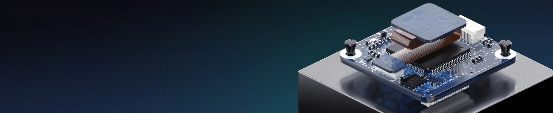
This article will look at interfacing DDR memory with FPGAs from a system-level and schematic point-of-view. As a practical example, we will look at an AMD/Xilinx Spartan-7-based audio DSP design (named ‘Xerxes’), which interfaces with some DDR2 memory.

Xerxes audio DSP hardware (AMD/Xilinx Spartan-7 FPGA with DDR2 memory)
Type of Memory
What type of memory we use is design-dependent. It depends on our memory capacity and memory bandwidth requirements, as well as what our FPGA of choice is capable of.
Generally speaking, most modern FPGAs can interface with DDR2 and DDR3 memory (and their low-power, low-voltage variants). Of course, faster DDR4 memory and above is also possible, but usually only for more advanced FPGAs.
Not only the maximum possible data rate is important, but also voltage and power requirements, package type, cost, and availability are important. This all needs to be considered early in the design stage.

DDR Memory Comparison (Source: synopsys.com)
When choosing our memory type, we also need to watch out for the speed grade of the memory device and the speed rating of the memory controller within the FPGA. We can choose to ‘derate’ our memory or controller, thus not running at full bandwidth, which in turn gives us more timing slack.

Typical Memory Derating Table (Source: AMD/Xilinx UG933)
Specifically for AMD/Xilinx FPGAs, I’d suggest downloading their Vivado IDE and playing around with the free Memory Interface Generator (MIG) IP.
This will quickly show you what memory types, speed grades, and compatible parts you can use.

Vivado MIG Compatible Memory Parts Example
You may ask, why did I go with DDR2 memory for the Xerxes board?
Even though it is a fairly old standard, using DDR2 memory meant I could use the already-available 1.8V regulator on the board (this powers other parts of the FPGA) and didn’t have to add in yet another separate regulator.
In addition, the Xerxes design doesn’t have particularly high memory bandwidth requirements, and thus a DDR2 interface was sufficient.
Furthermore, having a lower-bandwidth interface eases the PCB, termination, and timing constraints.
DDR Memory and FPGA Interface
After having chosen a suitable memory device, it’s time to connect this to the FPGA in your schematic.
First, we need to choose a suitable bank. If you’re using a 16-bit wide (or lower) data interface, for most FPGAs this can usually fit in one bank. If not, we need to split the memory interface across multiple banks.
For simplicity, we’ll go with a 16-bit wide memory interface, as is the case with the Xerxes board. Choose a free bank that is able to run off of the same voltage as the DDR memory itself (in the Xerxes case, this is bank 34 at 1.8V due to using DDR2 memory).

FPGA Bank 34 With Appropriate Decoupling Running From the 1.8V Supply
For AMD/Xilinx FPGAs, using the Vivado and MIG tools, getting the pin-out for our DDR memory is very straight-forward. The tool either suggests a suitable pin-out for that bank, or we can assign pins manually and verify the pin-out.

Vivado MIG Pin-Out Tool
If you manually configure the pin-out, ensure that the individual DDR byte lanes have the same bank byte number and that the differential strobes are on the differential FPGA DQS-capable pins.
Remember that the pin-out will probably be adjusted during the PCB layout and routing stage. Thanks to the FPGA’s flexibility, swapping pins during the PCB design process can simplify routing and minimize layer transitions.
For this example, as we are running from a single bank, we must use the internal VREF, limiting the maximum memory bandwidth.
Additionally, we need to watch out for clocking. Ideally, the clock source should be in the same bank attached to a clocking-capable pin (or pins if using a differential clock source).
Finally, make sure to use vendor tools to verify the design and timing. Then with the initial pin-out in place, in your schematic, define net classes, differential pairs, and rules, and use color coding to make your PCB design life easier.

FPGA Bank 34 DDR2 Connections and Clock Source
For a single device, we simply need to do point-to-point connections on the DDR memory component.
Termination should be present on the address/command/control signals (ACC); however, for lower data rates we can very often get away without this. I do always add termination on the differential clock pair. The data byte lanes are internally terminated on both ends.
Recommend 4.7k pull-down resistors are placed on the CKE, ODT, and optionally the CS# lines.

DDR2 Memory Module Signal and Power Connections
Finally, the memory module needs to be powered of course. In the case of the Xerxes board, the DDR2 module is connected to the same 1.8V regulator as our FPGA bank 34. Appropriate decoupling is required – as a rule of thumb, if not specified otherwise in datasheets or application notes, aim to use one small (~100nF) capacitor per two VDD pins and one, larger bulk capacitor per ten VDD pins.
The VREF pin voltage can be generated via a simple potential divider with a filtering capacitor, as shown in the image above.
Outro
In this article, we’ve outlined the basic strategies for incorporating external, non-volatile DDR memory in our FPGA-based designs from a system-level and schematic-level point-of-view.
Remember that these are the absolute basics, and depending on your system requirements, the design will be much more involved. Especially, if you plan on using faster memory parts and interfaces, and multiple modules.
When designing advanced FPGA- and DDR-based systems, make sure you are utilizing the tools and features contained in world-class ECAD tools such as Altium Designer. Make sure to secure your free trial of Altium Designer and Altium 365 here.

About Author
Related Resources
Related Technical Documentation
Design to Release, Without the Friction
- Keep reviews tied to the right version
- Reduce handoff confusion and rework
- Spot sourcing and release risk earlier
- Work solo, share when needed
Get Started
Thank you, you are now subscribed to updates.