

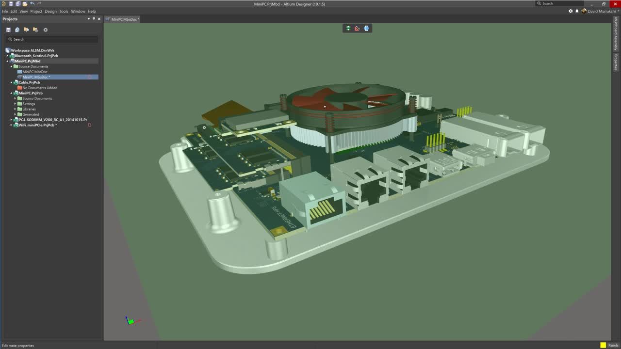
Altium Designerの高度なマルチボード表示機能を使用して、容易に筐体と適合したり、形状や機能を把握できます
This page provides quick reference information about the drawing objects that can be used in the Draftsman editor when creating manufacturing documentation for your design, giving you a means to quickly navigate to more detailed information about each. A Draftsman-based manufacturing drawing document can be added to a PCB design project (*.PCBDwf), a harness design project (*.HarDwf), or a multi…
以下のセクションでは、Draftsman Editorに特有のショートカットキーを紹介します。ショートカットキーのアクセスと編集、Altium環境全般のショートカット、アクセラレータキーに関する一般情報については、Altium Designer ショートカットキーを参照してください。 ショートカットキーのリストを見る際には、以下の点を念頭に置いてください: ショートカットを参照する際、プラス記号 (+) の使用は、指示された順序でキーボード上の複数のキーを押し続けることを意味します。例えば、Shift+F1 は Shift キーを押し続けてから F1 キーを押すことを意味します。同様に、Shift+Ctrl+PgUp は Shift キーを押し続け、同時に Ctrl キーを押し続け、PgUp キーを押すことを意味します。 標準的なマウスボタンの使用については…
親ページ: 設計ドキュメントの効率化を図る製図 製図ドキュメントは、ページのプロパティを定義するためにテンプレート(シートテンプレート、*.DwsDot)を使用でき、新しいドキュメントには、あらかじめ定められた内容(ドキュメントテンプレート、*.DwfDot)の範囲を使用できます。これらのタイプのテンプレートは、エディタで現在開いているPCB図面ファイル(ファイル拡張子PCBDwf)から、テンプレートタイプのいずれかとしてドキュメントを保存することで作成できます。テンプレートドキュメントは再度開いて編集し、内容とプロパティを変更するために保存できます。 シートテンプレート シート(ページ)テンプレートには、ページのグラフィック情報が含まれています。これには、シートのサイズ、パラメータ、ゾーンと境界の設定が含まれます。エディタのグラフィックツール(線、長方形、円、テキストなど…
Parent page: Streamlining Board Design Documentation with Draftsman Draftsman provides a range of graphical element tools that can be used to place basic, free-form drawing elements in a document. The tools are accessed from the main Place menu, from the Graphical Tools drop-down menu () on the Drawing Annotations toolbar or the graphic tools drop down on the Active Bar. Place a graphic element…
A Draftsman document allows Bill Of Materials (BOM), Drill and range other data tables to be placed on the drawing and subsequently configured in the Properties panel. The tabular data is directly derived from the project PCB files and provides a simple, visual way to convey crucial information for the PCB fabrication and assembly processes. The BOM/Drill/Table placement options are available…
親ページ: ドラフトマンでのボード設計文書の効率化 寸法 オブジェクトの寸法グラフィックは、ボードビュー(組み立て、製造、断面、詳細など)に配置して、オブジェクトの輪郭の長さ、サイズ、角度、または指名されたオブジェクト間の距離を示すことができます。寸法グラフィックを配置するには、Placeメニューまたはアクティブバーの寸法ドロップダウンから、希望のタイプを選択します。 寸法ツールはアクティブバーにあります。メニューを開くには、寸法ボタンをクリックしてしばらく押し続けてください。 計測単位: ドラフトマン文書に適用される単位系(メートル法またはインペリアル)は、Document OptionsモードでPropertiesパネルのUnits設定によって定義されます。しかし、線形/径方向寸法、ドリル/BOMテーブル、レイヤースタックの凡例などの個々のオブジェクトについては…
Parent page: Streamlining Board Design Documentation with Draftsman Draftsman provides a range of additional drawing and annotation tools designed to add important information to a Draftsman drawing document. These include both automated note and highlighting systems. The Active Bar (positioned at the top of the design space) offers a range of drop-down menus that include placement commands for…
Parent page: Working with Views Along with the Board Assembly View and the Board Fabrication View, Draftsman suggests a number of additional automated design views to complete your PCB drawing. Board Section View A Draftsman Board Section View provides a profile slice, or sectional, drawing taken from a nominated 'cut' point through a placed Board Assembly View. The section view generator takes…
Draftsman の基板製作用ビュー(Place » Board Fabrication View)は、PCB プロジェクトの未実装(ベア)基板を上面または下面から見た状態で自動生成されるグラフィック合成図です。図面データは指定された物理基板レイヤーから取得され、必要に応じて追加レイヤーを表示できます。 PCB の上面レイヤーと下面レイヤーを示す、配置済みの 2 つの基板製作用ビュー さらに詳細を表示するには、基板製作用ビューから 基板詳細ビュー を作成することを検討してください。 配置済みの基板製作用ビューの図面表現は、デザインスペースでそのビューを選択すると Properties パネルで設定できます。一般的なビューのプロパティは、パネルの General タブ()で設定します。 Scale Scale、 Use Custom Scale…
親ページ:ビューの操作 ドラフトマンボードアセンブリビューは、アクティブなPCBプロジェクトのボードアウトライン、カットアウト、穴、およびコンポーネントグラフィックスに加えて追加の注釈を含む自動グラフィックコンポジットです。その描画表現、含まれる情報、およびデータソースは、Propertiesパネルで設定可能です。 配置されたボードアセンブリビューは、移動、スケーリング、異なる側面からの表示が可能です。 指定されたソースプロジェクトのPCBのアセンブリビューは、アクティブバー上のボタンを選択するか、Placeメニューオプションを通じて文書に配置されます。コマンドを起動すると、ソースPCBファイルから描画データが取得され、カーソルが十字線に変わり、レンダリングされたボードアセンブリビューがカーソルに添付されます。カーソルを希望の位置に移動してからクリックして配置を確定します。 描画データは…
Easily synchronize designs between Altium Designer and top MCAD systems.